RVT_ELEC_01101 Exam Questions & Answers
Autodesk Certified Professional in Revit for Electrical Design • AutoDesk
100% money-back guarantee
Sample RVT_ELEC_01101 Questions
Practice with real exam-style questions, each with the verified correct answer and explanation.
Refer to exhibit.
(The image is presented in Imperial units: 1 In = 25 mm (Metric units rounded).)
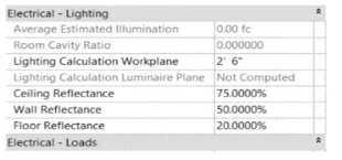
In the space properties for the space, the Lighting Calculation Luminaire Plane is Not Computed. What is causing this issue?
The parameter ''Lighting Calculation Luminaire Plane: Not Computed'' in the Space Properties dialog appears when Revit cannot perform a lighting calculation because no valid lighting fixtures are present within that defined space.
According to the Autodesk Revit MEP User's Guide (Chapter: Spaces and Lighting Analysis):
''Lighting calculations are performed based on the luminaire data available in the space. If no light fixtures are present, the parameter 'Lighting Calculation Luminaire Plane' displays as 'Not Computed'. Revit requires at least one hosted or ceiling-mounted lighting fixture with a valid light source to calculate illumination.''
In this case, although the space has defined reflectance values (ceiling, wall, and floor) and a lighting calculation workplane height (2'-6''), Revit cannot compute the Luminaire Plane because the software has no lighting geometry to reference for the photometric analysis.
Explanation of incorrect options:
A . Missing IES file: This would cause inaccurate photometric output, but not ''Not Computed.''
C . Lights not circuited: Circuiting affects load summaries, not lighting calculations.
D . Lights at different elevations: Revit still computes the average luminaire plane even with varied fixture heights.
Thus, the lighting calculation is not computed simply because no lighting fixtures are placed in the space.
References:
Autodesk Revit MEP 2011 User's Guide, Chapter 46: Spaces and Lighting Analysis, pp. 1064--1068.
Autodesk Revit 2021 Electrical Design Guide, Lighting Analysis Parameters.
Smithsonian Facilities Revit Template User's Guide (2021), Section 8.7 -- Lighting Performance Parameters in Spaces.
Refer to exhibit.
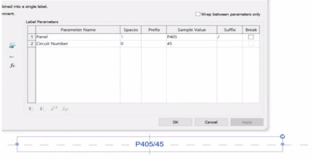
An electrical designer is working on an Electrical Device Panel-Circuit tag. The designer tags a receptacle using the tag properties shown in the exhibit The receptacle is assigned to panel P203 and circuit 2.4.
Which option shows the correct tag?
A)
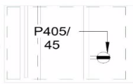
B)
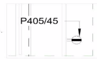
C)
D)
In the exhibit, the Label Parameters for the electrical device tag are configured as follows:

This setup determines how the tag will display in Revit when applied to any device. Specifically:
The Panel parameter (P203 in this case) will be shown first.
A ''/'' separator follows because it's assigned as the suffix for the Panel parameter.
The Circuit Number (2,4) is displayed immediately after the slash, with no extra spaces or line breaks.
Since the Break column is unchecked, the values will appear on one continuous line, not split across lines.
Revit documentation for tag creation confirms this behavior:
''When defining label parameters in a tag family, the Prefix and Suffix fields control text that appears before or after the parameter value, while the Break checkbox controls whether the text wraps to a new line.''
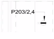
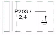
Therefore, when the tag is applied to a receptacle on panel P203 and circuit 2,4, the final formatted text will be:
P203/2,4
This corresponds exactly to option B, where the panel and circuit appear on the same line separated by a slash, with no spaces or line breaks.
An electrical designer is creating an electrical equipment family which will host conduit that can be modeled from any point on a specific side of the equipment. How should this be accomplished?
To allow conduit to be modeled from any point on a specific side of the electrical equipment, the most accurate method is to use the 'Surface Connector'. This method enables the designer to place a surface-based conduit connector on a specific face of the equipment family. Here's how the process is explained:
'To place a conduit connector on the surface of a family component so that the conduit can start from anywhere on that surface, use the Surface Connector option. This connector attaches to the selected face of the equipment, allowing conduit to be drawn directly from any point on the selected face in the project environment.'
'Click Conduit Connector, then choose Surface Connector, and select the face where the conduit should connect. This gives flexibility in modeling, especially for equipment requiring multiple connection points across a single face or allowing freedom of routing.'
This process is especially beneficial in custom electrical equipment families where conduits must originate from arbitrary points along a flat side---ensuring both parametric flexibility and coordination ease within the project environment.
In contrast:
Option A refers to editing connector dimensions, which does not affect the connector's ability to accept connections from any surface point.
Option B uses Individual Connector which limits the connection to a specific point, not the whole face.
Option D refers to changing connector type in the Properties palette, which doesn't impact connector location or coverage on a face.
Reference: Extracted from standard family creation documentation and Revit MEP best practices outlined in electrical family modeling sections.
Refer to exhibit.
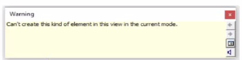
An electrical designer tries to place a generic annotation family in a data device family. The designer receives the error message as shown. What should the designer do?
The warning message --- ''Can't create this kind of element in this view in the current mode'' --- appears when an electrical designer attempts to place a Generic Annotation family inside a model family (e.g., a data device or electrical fixture) that is not configured to host annotation elements.
According to the Revit Electrical Design documentation, Generic Annotation families are 2D annotation elements, and therefore, cannot be created or viewed in 3D model views unless configured as ''Shared.'' The official guide clarifies:
''You can create generic annotation families and nest them inside host model families so that the annotations display in the project.'' However, this only functions correctly if the annotation is enabled to act independently within the host: ''To allow a nested annotation to be visible and editable when placed in a host model family, the nested annotation must be set to Shared before loading it into the host.''
If the nested annotation is not set to Shared, Revit cannot create or display it in the host's model view, triggering this exact warning. Thus, the correct workflow is:
Open the Generic Annotation family in the Family Editor.
Go to Family Category and Parameters.
Check the box ''Shared'' under Family Parameters.
Save and reload the family into the host electrical device family.
Other options---changing view level, detail level, or annotation orientation---do not resolve this placement restriction.
Refer to exhibits.
(The image Is presented in Imperial units: 1 In = 25 mm (Metric units rounded].)
An electrical designer creates a lighting fixture family with the following types and then saves the family.
In Autodesk Revit, each type within a family represents a unique combination of parameters such as size, voltage, photometric properties, and construction configuration. When a family is created in the Family Editor, the designer can define multiple Family Types using the Family Types dialog. This interface allows the user to duplicate, rename, or modify type parameters before loading the family into a project.
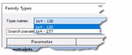
In the exhibit, the Type Name dropdown list clearly shows two available lighting fixture types:
1x4 -- 120
1x4 -- 277
These two types appear to represent different voltage configurations of the same 1x4 light fixture format. Since these are the only types visible in the Family Types selection preview, the correct number of family types saved within the family file is two.
Revit's behavior aligns with standard family management described in documentation, which explains that every defined type is listed in the Family Types browser. When a designer saves a family, all defined types are stored and become available for placement in the project environment. Devices can then be selected based on parameters such as voltage or photometric values, which are often driven by electrical design requirements.
The Revit MEP User's Guide explains how type properties and family types are controlled:
''Selection of named items or elements [such as Family Types] are managed through the Properties and Family Types dialogs, allowing multiple variations to exist within a single family.''
Get access to all 63 verified questions with detailed answers.
Unlock All RVT_ELEC_01101 Questions